As part of a hackathon, we created Candid Camera, a home security platform that uses the Bezirk Middleware.
Candid Camera monitors a door to catch unsolicited strangers by sending you a video whenever an stranger opens it.
This technology could also be used to answer the age-old question, "Who stole the cookies from the cookie jar?" or help monitor a filing cabinet containing particularly sensitive information. In these settings, a knowledgeable thief might be able to first cover or otherwise disable the camera(s), leaving only timing and possible intent information.
##Advantages:
- This Internet of Things system is significantly lower cost than other comparables. You only need:
- An inexpensive Wi-Fi-enabled Arduino/Raspberry Pi, simple reed switch (possibly also a resistor), and magnet.
- A low-power Bluetooth beacon (Estimote is used in this prototype; can also change the code for another proximity sensor such as RFID).
- An Android smartphone (cost estimates assume you already have this).
- A camera device. With current code, this could be a Windows computer with a webcam attached; a wide range of cameras and IP cameras are supported. In a future edition, you can replace this with an old Android device like those you can buy inexpensively on eBay, that doesn’t even need a carrier plan.
- Mounting hardware such as tape, screws, or adhesive tack to hold up the door sensor, camera, and/or wires (if your devices need any), as well as wire-covering paper in a color that matches the walls for more asthetically pleasing installations.
- You don’t have to pay a monitoring company, and you don’t have to have the camera directly accessible from the public Internet or directly visible to monitors 24/7.
- Fewer innocuous alarms than simpler activation systems: You don't need alerts every time you (or others you wish to authorize) are opening or passing through the door.
- Home-scalable: In a more configurable future edition, you can have multiple sensors and associate each camera with one or more specific door sensors. You can also have multiple cameras, and even different types of cameras running on different platforms, triggered on any specific door sensor. You will be able to add or remove (subscribe/unsubscribe) them without having to change anything on the controller.
- Not Cloud-Dependent: This system does not absolutely rely on the "cloud" or a connection to the broader Internet. Components communicate with one another over the local wireless network via Bezirk middleware. Connection to the broader Internet is only needed for remote notifications and optional cloud backup of captured video (which most providers re-attempt after an Internet outage without requiring explicit user intervention).
###Future improvements:
- Better UI including configurable parameters and control.
- Configurable authorization list (with revocation capabilities) listing specific phones that count as "recognized," instead of relying solely on Wi-Fi authentication controls.
- Improved hardware (e.g. real reed switch instead of button prototype) and conversion of Arduino + serial sensor piece to Wi-Fi-enabled Raspberry Pi to send Bezirk events directly and improve the form factor as well as reduce cost. The Arduino + serial sensor hardware simulation used here already exceeds hackathon specs allowing software simulation of devices.
- Camera client for Android that uses the camera on an Android device, and/or other adapters that can process camera events. Again, writing the adapter allowing us to control real Windows camera devices exceeded hackathon specs.
- Enhanced notifications including options for SMS, for including a direct link to the video (which may be stored on a cloud platform like Dropbox, Google Drive, etc. accessible to only authenticated users) and/or a still image attached to MMS or e-mail.
- Simplified installation.
PLEASE NOTE: This is a HACKATHON PROTOTYPE. It is NOT yet well tested and has NO WARRANTY WHATSOEVER and you should NOT rely on it as-is. If you try it, it’s at your own risk. Copyright is retained by the authors.
##PROTOTYPE INSTALLATION INSTRUCTIONS The system has four main software components:
- Door sensor: Detects and broadcasts when door opens or closes.
- Smartphone: If in range and receiving event notification that “door opens,” broadcasts message indicating whether or not it was recently in the vicinity of the doorway.
- Controller: Listens for door events and starts recording; cancels recording if authorized phone sends notice it was in the vicinity of the door; stops recording a certain amount of time after the door is closed (subject to a maximum recording length in case no “door closed” signal is received within a few minutes after the “door open” event); notifies owner.
- Camera(s): Listens to recording instructions from controller.
Since this is a distributed application, make sure all of the applications are connected to the same Wi-fi before running the application. The message-passing middleware will also fail if the network enforces client isolation.
In a single-camera setup, it is suggested to run the controller on the same device as the camera. In a multi-camera setup, the controller can be run on any camera. It can also be run on the processor attached to the door sensor, if that processor has sufficient computing resources. If the door sensor is driven by a full PC that also drives an IP camera elsewhere on the network, that same machine should also run the controller (and camera listener). The controller should NOT be run on a mobile device that might be missing from the network at the time of a possible intrusion. The software separation between controller and camera(s) permits use of multiple cameras, that may each have a different angle on the scene. It is possible to eliminate the Bezirk interface between the controller and camera and have a separate controller for each camera, but this may lead to inconsistencies and extra notifications.
First, follow these instructions for general system setup.
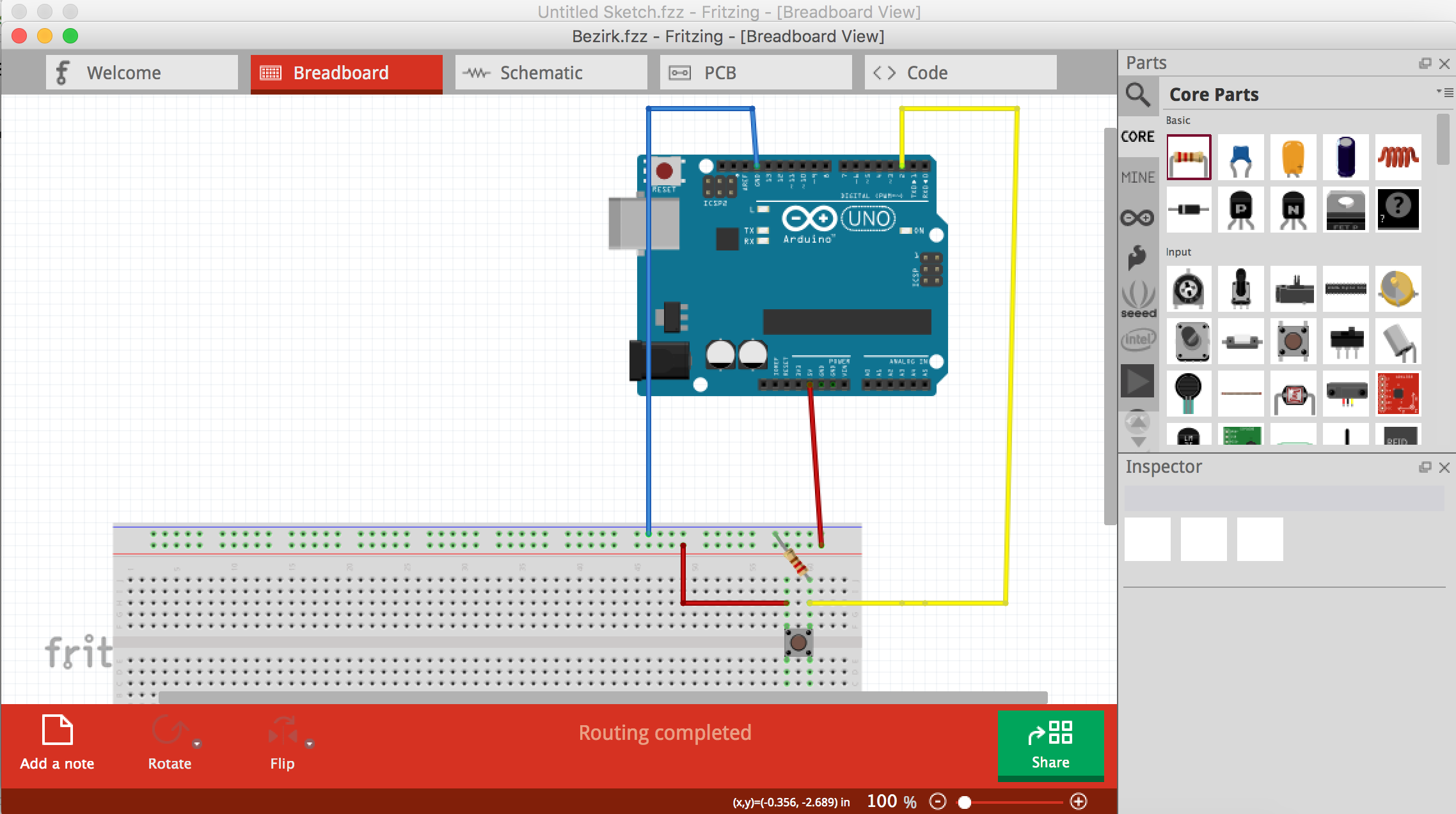
- Build the circuit. An Arduino schematic for the door sensor can be found here where the switch shown should be a magnetic reed switch. (A more detailed view of a pushbutton-switch prototype is here). If power draw is a primary concern, "Normally Closed" switches will be open most of the time because the door will be in a "closed" state and the magnet attached to it will keep the reed switch open. However, such switches are unable to distinguish between a closed door and a destroyed circuit, while "normally open" switches more appropriatey interpret a partially destroyed circuit similarly to "door open."
- Install Arduino IDE, if you haven't already. This demo also uses RXTX for communication with the Arduino, which may require some separate installation. Note that if you are using Windows and installing a 32-bit RXTX DLL (C:\Windows\System32\rxtxSerial.dll) that will not work with a 64-bit JVM; use a 32-bit JVM or try a 64-bit version of RXTX (potential source here).
- Download this file and open it in Arduino IDE.
- In Arduino IDE, select Tools->Board: “Arduino/Genuino Uno” (if you are following the tutorial closely and using such a board, otherwise select your board).
- In Arduino IDE, select Tools->Port: and pick the one with your board attached to it (e.g. "COM4" on Windows or "/dev/cu.usbmodem 1411" on Mac.) It might say "(Arduino/Genuino Uno)" after the port name. Make note of the port name.
- Press the Upload button to upload the code to Arduino.
- Download this directory. In Android Studio, choose File -> New -> Import Project and select that directory on your local hard drive.
- Open the file "SerialTest.java" (under src/main/java) and look for the definition of
String PORT_NAMES[]. Change the one for your operating system to match the port you noted above. - Run the main() method of this file. This should create a thread that monitors the door switch and sends events when the switch state changes.
The smartphone software and installation instructions can be found here.
- Download this directory and import it as a project in Android Studio.
- You may need to open Project View, expand the
libsdir, right click onmail.jar, and chooseAdd As Librarynear the bottom of the list. - The default setup is to record for 30 seconds after the door is closed, plus the entire time the door is open and any pre-trigger buffer, plus or minus communications delays, up to the maximum length configured for the camera under "Cameras" below. In listeners/RecorderController.java you can optionally change that 30 second parameter
recLengthAfterDoorClose. - Run RecorderController.main(). This should listen for door events and send events to the recorders (i.e. cameras) as appropriate.
- First, install iSpy for Windows on a Windows machine that will remain running while you wish the system to be active.
- In the iSpy interface, “Add” devices. You can add webcams that are plugged in locally, or IP cams and other video or microphone sources. After you add a device, in the Edit Camera or Edit Microphone dialog, take note of the number following “ID” in the title bar. In this dialogue, you can control advanced properties like adjusting camera color balance, exposure, rotation/mirroring, data directory, microphone association, etc.
- In the iSpy Edit box, especially if you are a paying subscriber, the Alerts tab allows you to optionally add actions like SMS or e-mail notification through iSpyConnect (instead of this system's controller) when e.g. recording starts or stops.
- In the iSpy Edit box Recording Tab, the Recording Mode option should be set to No Recording; this system uses external triggers. "Max. Record Time" and "Buffer" time-length settings can optionally be changed in this tab as well.
- In iSpy, Options->Settings->Storage, optionally change the media directory to one that you have automatically synced to a cloud storage service via its desktop client. Future versions may implement cloud storage and video hosting site APIs to enhance configurable privacy control.
- In iSpy, Options->Settings->IP Access->IP addresses allowed, add the local IP address of the machine running the camera event listener launched below. If you’re running the camera event listener on the same machine (recommended), put in “127.0.0.1.”
- In iSpy, Options->Settings->Options, optionally check out other settings like “Restart If Crashed,” “Run on startup,” “Password Protect,” or Options->Settings->Connection Alerts, if you want those features.
- Download and import (into Android Studio) the same project folder you did for the controller, if you’re running this camera listener on a different machine from the controller.
- If you’re not running this camera listener on the same machine as iSpy (note you should still be at least on the same local network), change the IP address stored in
String serverAddressearly in CameraControllerZirk.java. - In the function
callActionOnEachCameraInArea, you may need to change the value ofoidto match the iSpy object id you noted earlier. See comments there about how to adjust for having standalone microphones or control multiple iSpy cameras, if applicable. - Run CameraControllerZirk.main() (in the “listeners” subpackage). This will create a thread listening for recording instructions and adapting them for iSpy instructions. Note: This prototype adapter is less robust than more fully developed Bezirk adapters typically are, but in at least some common cases works a lot better than having no camera adapter.