- Library for aruco marker detection and pose estimation, compatible with ROS.
- Multi marker pose estimation, use as many markers as possible to improve the performance of the system.
- Detection is not affected by lighting conditions (can be used for low light and high noise tracking).
Aruco markers are geometrically square, they have a black border and an inner grid that is used to store a numeric identifier in binary code.
A dictionary is used to identify the marker. The dictionary defines a set of rules used to calculate the marker identifier, perform validation and apply error correction.
We use the original aruco dictionary, that uses bits from the marker 2nd and 4th columns to store the marker identifier in natural binary code, the remaining bits are used for parity checking.
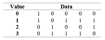
By analyzing the signature matrix, it is possibly to verify that it is not enough to guarantee that there is only one possible rotation for each marker in the we can see the marker 1023 that is horizontally symmetric.

The detection algorithm was implemented using the OpenCV library, since it pro-vides a large set of image processing algorithms. Figure 3 shows the steps applied to detect and identify markers.
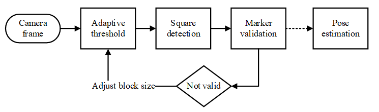
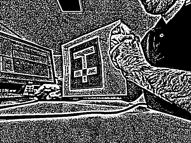
The algorithm starts by applying adaptive threshold [4] to the image, this algorithm consists in calculating for each pixel a threshold value using the histogram of its neighborhood. It is of particular interest for situations with multiple lighting conditions.
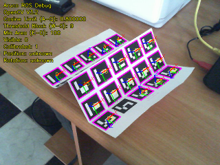
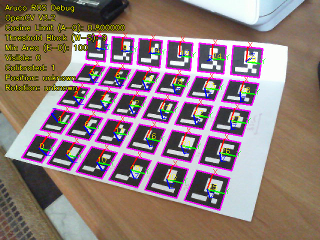
To determine the threshold block (neighborhood size), one block size is tested on each frame, the block size chosen is the average size from all block sizes were the maximum number of markers were found, the block size is retested when there are no markers visible. After threshold is applied to the image, we perform square detection contours are detected using a border-following algorithm [5], followed by the Douglas-Peucker contour simplification algorithm [6]. Based on the detected contours, the Quadrilateral Sum Conjecture is used as a criterion to detect squares. Even under significant perspective distortion a square is al-ways a convex quadrilateral. Our second criteria will be to make sure that the sum of the cosine of all inner angle is below a defined threshold. To filter noise a third criterion was added: all contours composing a geometry with an area bellow a defined threshold will be discarded. These three criteria allow to properly filter squares even under heavy distortion from the contour list. Figure 5 represents the obtained result for a maximum sum of cosine of 0.25 and a minimum area of 100px.

Perspective distortion is corrected in the detected squares, then they are resampled into a 7x7 matrix using linear interpolation, threshold is applied using the Otsu’s Binarization algorithm [7], at this point we obtain a matrix with the marker data in it. Fig-ure 6 represents the matrix obtained after the binarization process.

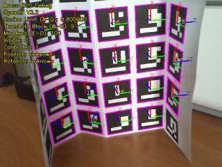
At this stage, the marker data is validated as aruco using the signature matrix. Markers might be detected in any orientation. The algorithm tests the data with different rotations (90º, 180º, 270º), if the marker is not recognized for any rotation it is then discarded. For pose estimation the method solvePnp from OpenCV was used, in iterative mode using Levenberg-Marquardt optimization [8]. To obtain the camera position, markers need to be registered into the program, a marker is represented by its identifier and a real-world pose (position and rotation). Corners obtained from all visible known markers are used to estimate the camera pose.
We created a testing environment to compare the developed solution with the ones already existing in the literature. Two test markers were printed: one Aruco maker and one ARTag maker. Both markers had exactly 20cm in size and the camera was placed on top of a box with the marker aligned with the camera. The marker was fixed with transparent tape. A measuring tape with a millimeter scale was used to measure the distance be-tween the camera and the markers. An image was taken for each distance tested and the markers were moved 30cm each time until none of the algorithms was able to detect the marker. Figure 7 represents some samples of the testing images used during the experiments. To measure the tolerance of the detector to perspective distortion a second testing environment was created. A marker was placed on a box and the camera was positioned 2.0 meters away. The marker was rotated in steps of 10º from 0º to 80º. Table 2 presents the results obtained for marker rotation showing that the proposed method performed better than the other two algorithms used for comparison, obtain-ing lower error.

Camera calibration was performed using a chessboard pattern and the values obtained were stored to be used for the tests. Figure 8 presents the results obtained. It is possible to observe an improvement in the maximum detection distance when using our algorithm.

- API documentation can be generated using Doxygen
- The ROS package is called "maruco" to void collision with the already existing aruco package.
- To install in your ROS project simply copy the aruco folder into your catkin workspace and execute "catkin_make" to build the code.
- To test with a USB camera also install usb-camera and camera-calibration from aptitude to access and calibrate the camera.
| Parameter | Description | Default |
|---|---|---|
| debug | When debug parameter is se to true the node creates a new cv window to show debug information. | false |
| use_opencv_coords | When set opencv coordinates are used, otherwise ros coords are used (X+ depth, Z+ height, Y+ lateral) | false |
| cosine_limit | Cosine limit used during the quad detection phase. The bigger the value more distortion tolerant the square detection will be. | 0.8 |
| theshold_block_size | Adaptive threshold base block size. | 9 |
| min_area | Minimum area considered for aruco markers. Should be a value high enough to filter blobs out but detect the smallest marker necessary. | 100 |
| calibrated | Used to indicate if the camera should be calibrated using external message of use default calib parameters | true |
| calibration | Camera intrinsic calibration matrix as defined by opencv (values by row separated by _ char) Ex "260.3_0_154.6_0_260.5_117_0_0_1" | |
| distortion | Camera distortion matrix as defined by opencv composed of up to 5 parameters (values separated by _ char) Ex "0.007_-0.023_-0.004_-0.0006_-0.16058" | |
| marker### | These parameters are used to pass to the node a list of known markers, these markers will be used to calculate the camera pose in the world.Markers are declared in the format marker###: " Ex marker768 0.156_0_0_0_0_0_0" |
| Topic | Description | Default |
|---|---|---|
| topic_camera | Camera image topic | /camera/rgb/image_raw |
| topic_camera_info | Camera info_expects a Camera Info message | /camera/rgb/camera_info |
| topic_marker_register | Register markers in the node | /marker_register |
| topic_marker_remove | Remove markers registered in the node | /marker_remove |
| Topic | Description | Default |
|---|---|---|
| topic_visible | Publishes true when a marker is visible_false otherwise | /visible |
| topic_position | Publishes the camera world position relative to the registered markers as a Point message | /position |
| topic_rotation | Publishes the camera world rotation relative to the registered markers | /rotation |
| topic_pose | Publishes camera rotation and position as Pose message | /pose |
- OpenCV 2.4.9+
- Works with OpenCV 3.0+
- Previous versions of opencv 2 might cause problems.
- CMake
- ROS (indigo and later)
- cv-bridge
- MIT license (Available on GitHub page)