Auth: M. Fras, Electronics Division, MPI for Physics, Munich
Mod.: M. Fras, Electronics Division, MPI for Physics, Munich
Date: 27 May 2022
Rev.: 27 May 2022
- ARM GCC.
- GNU make.
- Firmware flashing tool lm4flash.
- Minicom terminal program.
- ARM GDB and nemiver graphical debugger.
- Python 3 and required modules.
- ATLAS MDT Trigger Processor (TP) Command Module (CM).
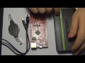
- TI Tiva TM4C1294 Connected LaunchPad Evaluation Kit board (for programming and debugging).
-
Install required packages. Example for Ubuntu 18.04.
ARM cross compiler toolchain.sudo apt-get install build-essential gcc-arm-none-eabi binutils-arm-none-eabi openocd
Firmware flashing tool.
sudo apt-get install lm4flash
Minicom terminal program.
sudo apt-get install minicom
ARM GDB and nemiver graphical debugger.
sudo apt-get install gdb-multiarch nemiver
Python 3 and required modules.
sudo apt-get install python3 python3-serial python3-tk
-
Preparations for firmware download.
Before installing the serial boot loader or downloading firmware, make sure that these conditions are met:- The TM4C1294 Connected LaunchPad™ Evaluation Kit is connected to an USB port of the PC.
- Its resistors R8, R10, R11, R15 and R16 are removed.
- Its header U6 is connected with a 10-pin 50 mil pitch flat cable to X113 of the CM.
- The jumpers X122, X123, X125 and X126 on the CM are in the correct position to connect the MCU SWD pins to the header X113.
- By default, always download the MCU firmware with no other power source provided to the CM. Alternatively, if the CM is powered with +12 V, cut the pin 1 of the flat cable to avoid connecting to power supplies.
-
Install the serial boot loader.
The serial boot loader provides firmware updates over the UART 5, which is connected to the SM SoC and is normally used for the user interface. In order to build and install the boot loader, change to theFirmware/Projects/boot_loaderdirectory and run this command:make installThe boot loader sits at address
0x0000of the flash, the main firmware image starts at address0x4000.The 9 MCU user LEDs indicate activity of the boot loader:
- The LED red 0 is on when the boot loader is active.
- The LED red 1 blinks during the countdown of the boot loader.
- During firmware download via the boot loader, the LEDs red 0 and red 1 are on and the remaining LEDs (yellow 0/1, blue 0/1, green 0/1/2) count up.
- When the firmware download via the boot loader is finished, all 9 MCU user LEDs blink 3 times indicating the end of the firmware download.
Note that the UART for the boot loader can be changed to UART 3, which is the front panel UART of the CM. Define
MDTTP_CM_MCU_BL_UART_FRONTPANELin the filebl_config.hto use UART 3 instead of UART 5 for the boot loader.Example minicom session for the serial boot loader:
***** MDT-TP CM prototype MCU boot loader version 0.0.1, release date: 27 May 2022 ***** Press any key to enter the boot loader menu. 5 4 3 2 1 Boot Loader Menu ================ Available commands: h Show this help text. b Start normal boot process. f Force MCU firmware download via the serial boot loader. r Reboot the MCU. > f ***** MDT-TP CM prototype MCU boot loader version 0.0.1, release date: 27 May 2022 ***** Waiting for firmware data... -
Compile and download the firmware project for hardware testing.
Change to theFirmware/Projects/cm_mcu_hwtestdirectory. Then clean the firmware project directory.make clean
This will wipe all compiled files and backups of source files from the project.
make mrproper
Build the firmware project.
make
Download the firmware.
make install
Compile and download a debug version of the firmware, then start the nemiver graphical debugger. Please note that there is a breakpoint set at the start of the program! This prevents it from running until the program is continued from the debugger.
make debug
After you have finished debugging, build and download the normal firmware version again.
make clean install
-
Firmware download via the serial boot loader.
Once the serial boot loader is installed, you can use it to download the main firmware. To do so, hit any key during the countdown after power-up to enter the boot loader menu. Then press the keyfto force a firmware update. Now quit the terminal program, change to theFirmware/Projects/cm_mcu_hwtestdirectory and download the main firmware via the serial boot loader.make sflash
If not yet done, this will automatically build the
sflashtool that comes with the TivaWare. After the firmware download, the MCU reboots automatically.Note that you may need to change the serial device in the
Makefilefrom/dev/ttyUL1to the one your computer uses to communicate with the UART of the MCU.Optionally, you can also run the
sflashtool from the command line:sflash -c /dev/ttyUL1 -p 0x4000 -b 115200 -d -s 252 gcc/cm_mcu_hwtest.bin
-
Communicate with the MCU using the minicom terminal program.
Create a file.minirc.cm_mcuin your home directory with this content:pu port /dev/ttyUL1 pu rtscts NoAdapt the
pu portto the serial input to which the MCU UART user interface is connected. This is usually/dev/ttyUL1when using the SM SoC UART and/dev/ttyUSB0when using the CM front panel mini USB UART.Launch minicom either by calling
make minicominside the firmware directory or by starting minicom from the shellminicom -c on cm_mcu. To quit minicom, pressCtrl-A, thenQ. To edit the minicom settings, pressCtrl-A, thenZ.Example minicom session:
TODO

- TM4C1290NCPDT product page
- Tiva C Series TM4C1290NCPDT Microcontroller Data Sheet datasheet (Rev. B)
- TivaWare™ Peripheral Driver Library for C Series User's Guide (Rev. D)