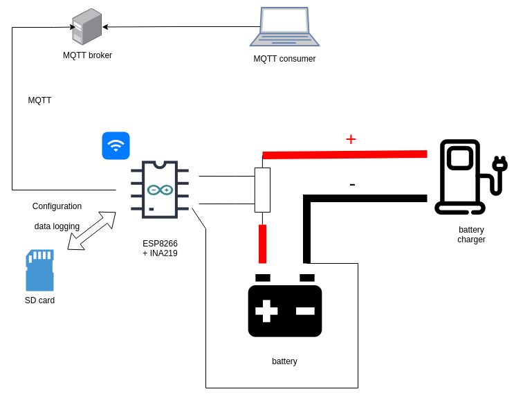
Acid-lead battery charging monitor registers electrical parameters during process of charging or discharging. Data is saved in CSV file on MicroSD card, and (or) sent via WiFi to LAN MQTT broker.
Configuration for WiFi and MQTT is loaded from MicroSD card config file example.
Registered parameters (average from 1 minute, measured every second):
- voltage,
- current.
Displayed parameters (measured every second):
- running time,
- voltage,
- current,
- power,
- calculated reserved capacity.
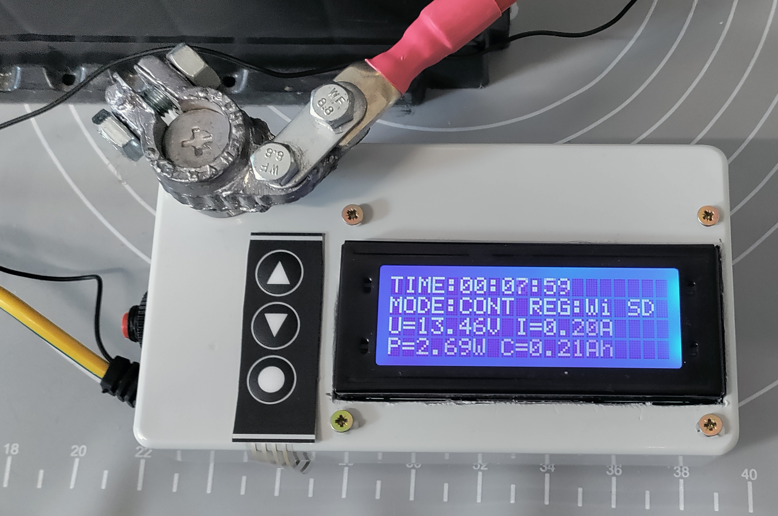
Data is collected in two modes:
- continuous mode - from manual start to power down
- auto - from manual start until the current is lower than 0.2A during 5 minutes
| Parameter | Value | Possible value* |
|---|---|---|
| Max. battery voltage | 16V | 31V |
| Min. battery voltage | 7V | 7V |
| Max. measured current | +/- 10A | +/- 15A |
*-requires change in preprocessor's macros
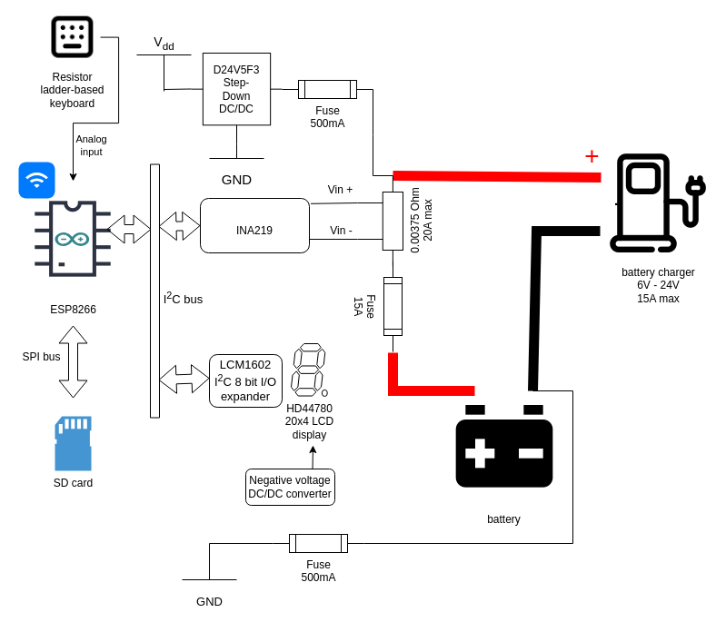
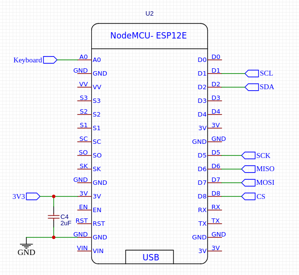
- NodeMCUv3 ESP8266-based board,
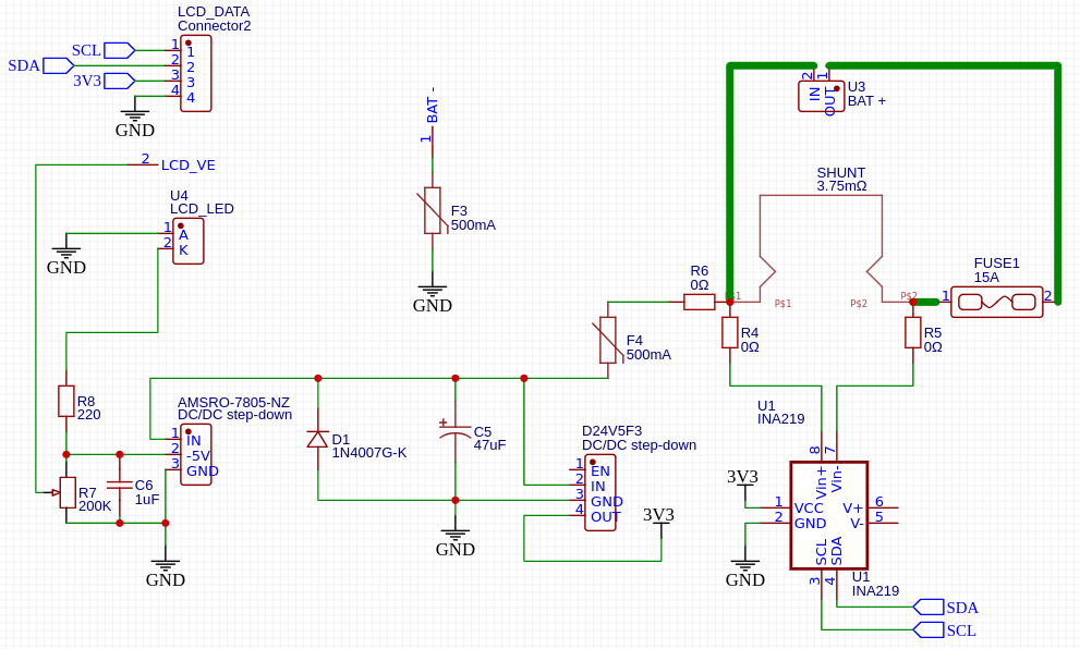
- INA 219 breakout board (removed 0.1Ω on-board shunt),
- 20A 75mV shunt,
- HD44780-compatible LCD 20x4 display,
- LCM1602 I²C I/O expander for HD44780 displays,
- MicroSD SPI bus card slot,
- D24V5F3 DC/DC step-down converter (3.3V),
- AMSRO-7805-NZ DC/DC step-down converter (-5V),
- 3-key membrane keyboard,
- 15A fuse, wiring and terminals able to handle 30A of current.
LCM1602 is connected to HD44780-compatible display without the following pings:
- VE (contrast voltage),
- Backlight LED anode,
- Backlight LED cathode.
Those are connected to separate, -5V power supply DC/DC converter.
Positive power for the circuit is connected to the high current input side of shunt (Vin+), with resettable 500mA fuse.
Ground is connected with low power cable via resettable 500mA fuse to negative battery connector. Fuse on the ground is needed, because there's no short circuit protection between the shunt and INA 219 board.
Diode D1 is connected in a way, that it shorts the circuit in case of the reverse polarity connection.
Reverse polarity connection is a very dangerous situation when connecting high capacity batteries, that's why additional fuse on the output connector is a must have (FUSE1 on the schematic).
Battery charger also has to be equipped with fuse on it's output.
Positive current reading means, that the current flows from charger to battery (battery is being charged).
Negative current reading means, that the battery is being discharged.
The device is powered from measured circuit and it's power consumption is around 250mW.
Minimal voltage for powering the circuit is 7V.
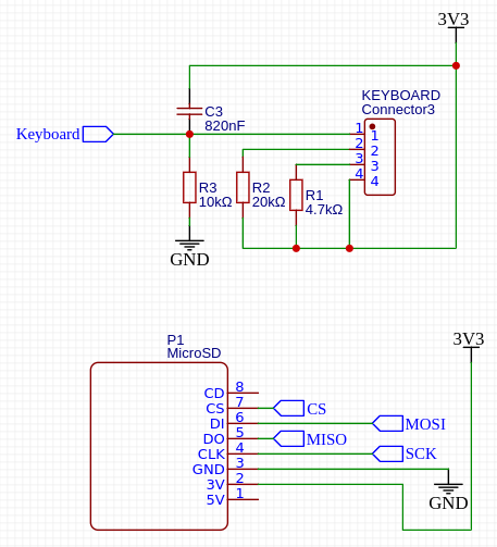
Membrane keyboard is connected via resistors ladder to analog input of the NodeMCUv3 system. This simplifies wiring a lot, but the situation, where more than one key is pressed simultaneously is not detected.
Capacitor C3 is used to eliminate key bouncing effect.
MicroSD is connected using SPI interface.
Power consumption is significantly higher during data reads and writes (around 20mA).
Please do not make shortcut by hard-wiring CS pin of MicroSD card reader to Ground - random voltage level on other pins during power-up or power down may destroy data on card.