
The Intervalometerator (aka "intvlm8r") is a flexible, low-cost time-lapse camera controller for DSLRs.
It came into being after we were unable to find a suitable time-lapse controller for a planned time-lapse shoot for which we wanted the image quality of a DSLR. The first unit deployed is recording the construction of our friends' house in rural New Zealand, off-grid and with no network connectivity.
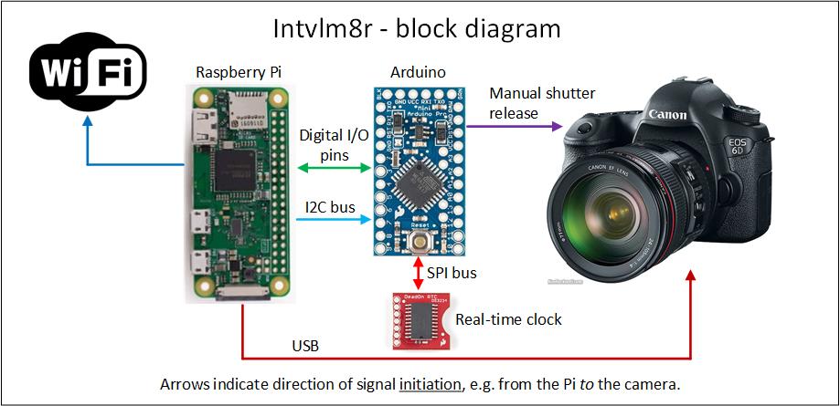
At its heart are two micro-controller boards, each serving a specific purpose. An Arduino Pro Mini is the master, with a battery-backed external real-time clock signalling it to wake the camera and fire the shutter. A Raspberry Pi Zero W provides a web-based "front-end" where all configuration and management takes place. An I2C communication bus between the micros handles the higher-level intercommunication, with 3 digital I/O lines between them providing 'wake' and 'shutdown' signalling. The digital I/O reduces the risk of drive corruption as the power-hungry Pi's power is applied and removed under the Arduino's control.
The Arduino's code ('sketch') is largely bespoke, whilst the Pi is totally reliant on and derived from both the gPhoto2 project, and python-gphoto2, Jim Easterbrook's Python interface to same.
With gPhoto and python-gphoto2 providing all the camera interfacing, the intent is that any camera compatible with these projects should be able to be used.
The intvlm8r has been tested primarily with Canon cameras and also a limited level of Nikon support. The unit deployed in NZ contains the 600D - read why on the Design Decisions page of the project's Wiki.
gPhoto (running on the Pi) is only used for the camera management, with the Arduino handling the core role of waking the camera and taking the shot using the camera's manual shutter input.
Check to see if your camera's been tested on this page (and please update it if you have tried).
From the web interface you select the days of the week to shoot, within what span of hours, and how many shots per hour. A typical building construction might shoot Monday through Friday, from 6am to 6pm, and take up to 60 shots an hour.
At least once each day, the Raspberry Pi copies the images from the camera, and if enabled by the user then uploads all the images to a remote store. The store destination can be an FTP or SFTP server, Dropbox, Google Drive or rsync. (Obviously, your intvlm8r requires a suitable private network or internet connection for this.)
Using commonly-available components, an intvlm8r controller with charger, battery, solar panel, waterproof Pelican case & mounts should see you with plenty of change from $AUD600 ($US440), a fraction of the cost of commercially-available equivalents. Add your DSLR and a lens and you're in business! See the Shopping list for the specifics.
Assuming the installation has WiFi or an Internet connection, the setup can be monitored and tweaked remotely. From your web-browser you can confirm that the camera is firing, backup the photos to the Pi, take a test image and adjust the available camera settings.
In an isolated setup, come within range and connect to the Pi Zero W's inbuilt WiFi Access Point for on-site management, without needing to crack the weatherproof seal on the Pelican case.
The intvlm8r can be set to send a regular 'heartbeat' message to a remote system to confirm its health. Should the heartbeats stop, an alarm can be raised. See the "setup heartbeating" page for more information.
The invtlm8r is designed for low-power operation. At rest the entire project consumes less than 1mA, enabling it to be powered by a common sealed lead acid ("SLA") battery and solar panel. Current consumption rises as the camera is woken to take a photo, and peaks when the Raspberry Pi is powered-on for management and file transfers.
Using pre-built micro-controller, clock and power supply boards reduces the complexity of assembly and the risk of errors. It also means you don't need a perfect set of eyes, nor the precision SMD soldering skills of a microsurgeon. The only discrete components on the veroboard shown here are resistors, a LED and the opto-isolators that electrically isolate the Arduino from the camera's shutter input - and none of that's surface-mount.
The intvlm8r's master clock is a SparkFun "DeadOn RTC Breakout". This high-accuracy real-time clock board carries a coin-cell battery to ensure it maintains the time even if the power supply fails.
The intvlm8r is powered from a standard 12V SLA battery and charger, providing a wide range of powering and charging options. Separate high-efficiency Pololu switched-mode power regulators run each operating unit on its own supply. Three separate on-board regulators provide:
- 3.3V for the Arduino & DeadOn clock
- 5.0V for the Raspberry Pi. An IO pin from the Arduino holds this supply's /SHUTDOWN input at 0V when the Pi is not running, significantly reducing quiescent power consumption.
- 7.5V for the Canon camera. The lower this voltage, the lower the battery can discharge without affecting the operation of the intvlm8r. The tested cameras run fine at this lower voltage, although report a battery at around 50% charge.
In theory, the 12V battery can discharge to ~8V before the camera will not be able take a photo, and much lower still before the Arduino and DeadOn clock lose power.
Should an extended period of bad weather result in the battery discharging to a point that it can no longer sustain operation, the intvlm8r will retain its settings in EEPROM (in the Arduino). Once the battery has sufficiently recharged, any pending alarms will be serviced (by taking a photo) and normal operation resumed.
Should the backup battery in the DeadOn RTC fail while the intvlm8r is not powered, the Arduino will lose its real-time clock. This will be detected on power-up and the Arduino default to an emergency program, shooting 4 images every hour of the day until the RTC can be reset through manual intervention.
Check out these documents for more information:
- Design Decisions. This provides a detailed explanation of some of the design decisions and compromises.
- Shopping list. All the items you need to make this. (Pre-built and pre-programmed PCBs are available on eBay if you're not one for soldering or programming micro-controllers.)
- Case assembly. A walk-through of preparing the Pelican case.
- PCB assembly. Putting the PCB together.
The Arduino's Sketch is in its own folder, and the Raspberry Pi's Python script and HTML pages can be found in their respective folders under RaspberryPi.
Please contribute to the project! It's coded in the Arduino's flavour of C++, with the Pi in Python, JavaScript, HTML & CSS, and there are improvements to be made across the board. Check out CONTRIBUTING.md for more info.
- Greig and Rocky.