btt_main/master


![]()
Important information related to BigTreeTech's TFT touchscreen 3D printer controllers
Only the TFT's listed below are currently supported. Trying to install the firmware on a TFT which is not supported can harm the hardware.
BTT TFT
BTT_TFT24_V1.1

BTT_TFT28_V1.0 and V3.0

BTT_TFT35_V1.0, V1.1, V1.2, V2.0, V3.0, E3_V3.0 and B1_V3.0

BTT_TFT43_V3.0

BTT_TFT50_V3.0

BTT_TFT70_V3.0
MKS TFT Warning: BTT does not officially provide MKS TFT hardware support, MKS TFT is maintained by open source contributors, and BTT does not bear any risk of MKS TFT hardware using this firmware
MKS_TFT28_V3.0 and V4.0

MKS_TFT32_V1.3 and V1.4
Firmware source: https://github.com/MarlinFirmware/Marlin/releases
Minimum Marlin firmware version: 2.0.8.1
Distribution date: 2021-05-15
In order the TFT firmware is able to provide all of its functionalities/features, the following options must be enabled in Marlin firmware.
General options which MUST be activated:
EEPROM_SETTINGS (in Configuration.h)
BABYSTEPPING (in Configuration_adv.h)
AUTO_REPORT_TEMPERATURES (in Configuration_adv.h)
AUTO_REPORT_POSITION (in Configuration_adv.h)
M115_GEOMETRY_REPORT (in Configuration_adv.h)
M114_DETAIL (in Configuration_adv.h)
REPORT_FAN_CHANGE (in Configuration_adv.h)
Options to support printing from onboard SD:
SDSUPPORT (in Configuration.h)
LONG_FILENAME_HOST_SUPPORT (in Configuration_adv.h)
AUTO_REPORT_SD_STATUS (in Configuration_adv.h)
SDCARD_CONNECTION ONBOARD (in Configuration_adv.h)
Options to support dialog with host:
EMERGENCY_PARSER (in Configuration_adv.h)
SERIAL_FLOAT_PRECISION 4 (in Configuration_adv.h)
HOST_ACTION_COMMANDS (in Configuration_adv.h)
HOST_PROMPT_SUPPORT (in Configuration_adv.h)
Options to support M600 with host & (Un)Load menu: (Options to support dialog with host as pre requisite)
NOZZLE_PARK_FEATURE (in Configuration.h)
ADVANCED_PAUSE_FEATURE (in Configuration_adv.h)
PARK_HEAD_ON_PAUSE (in Configuration_adv.h)
FILAMENT_LOAD_UNLOAD_GCODES (in Configuration_adv.h)
Options to fully support Bed Leveling menu:
Z_MIN_PROBE_REPEATABILITY_TEST (in Configuration.h)
G26_MESH_VALIDATION (in Configuration.h) (in Configuration.h)
Z_STEPPER_AUTO_ALIGN (in Configuration_adv.h)
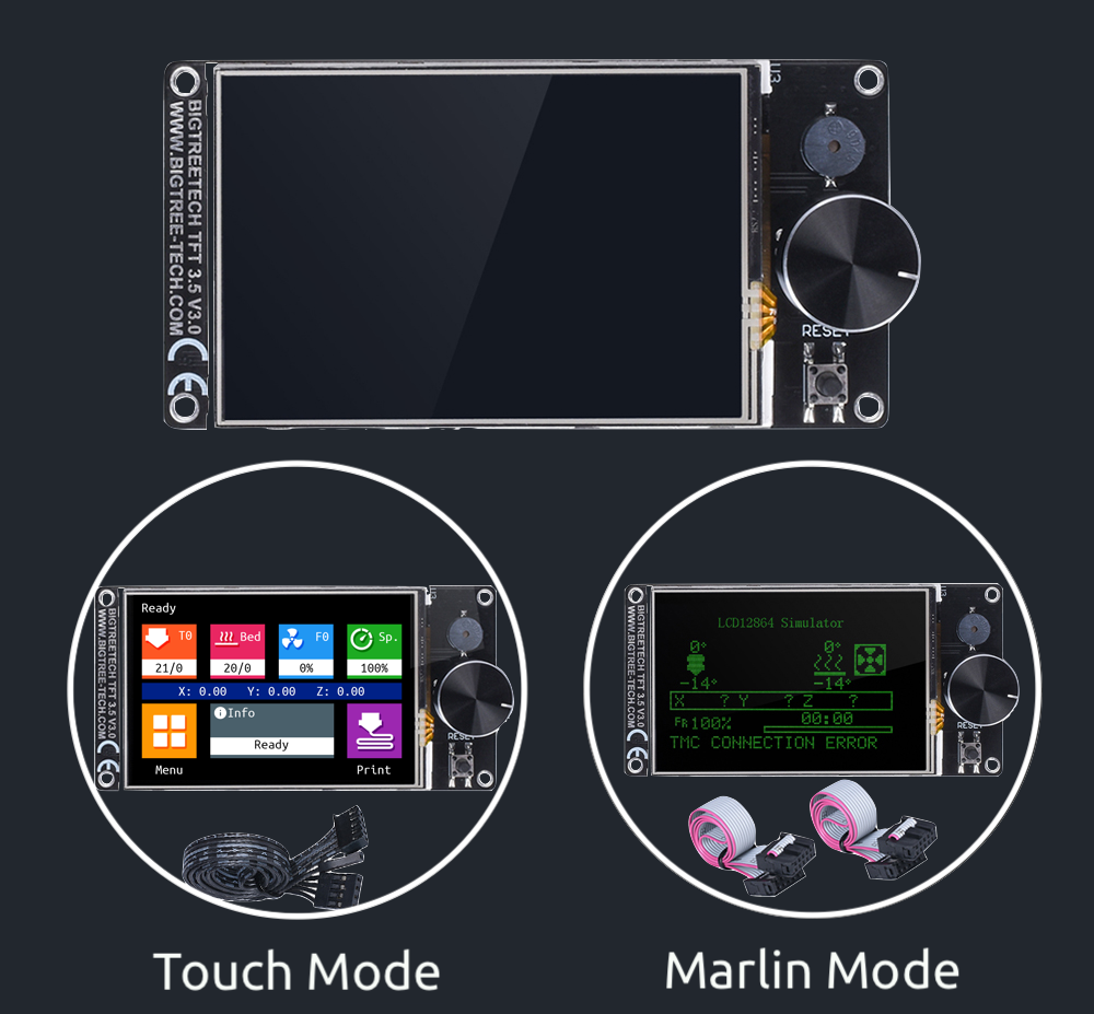
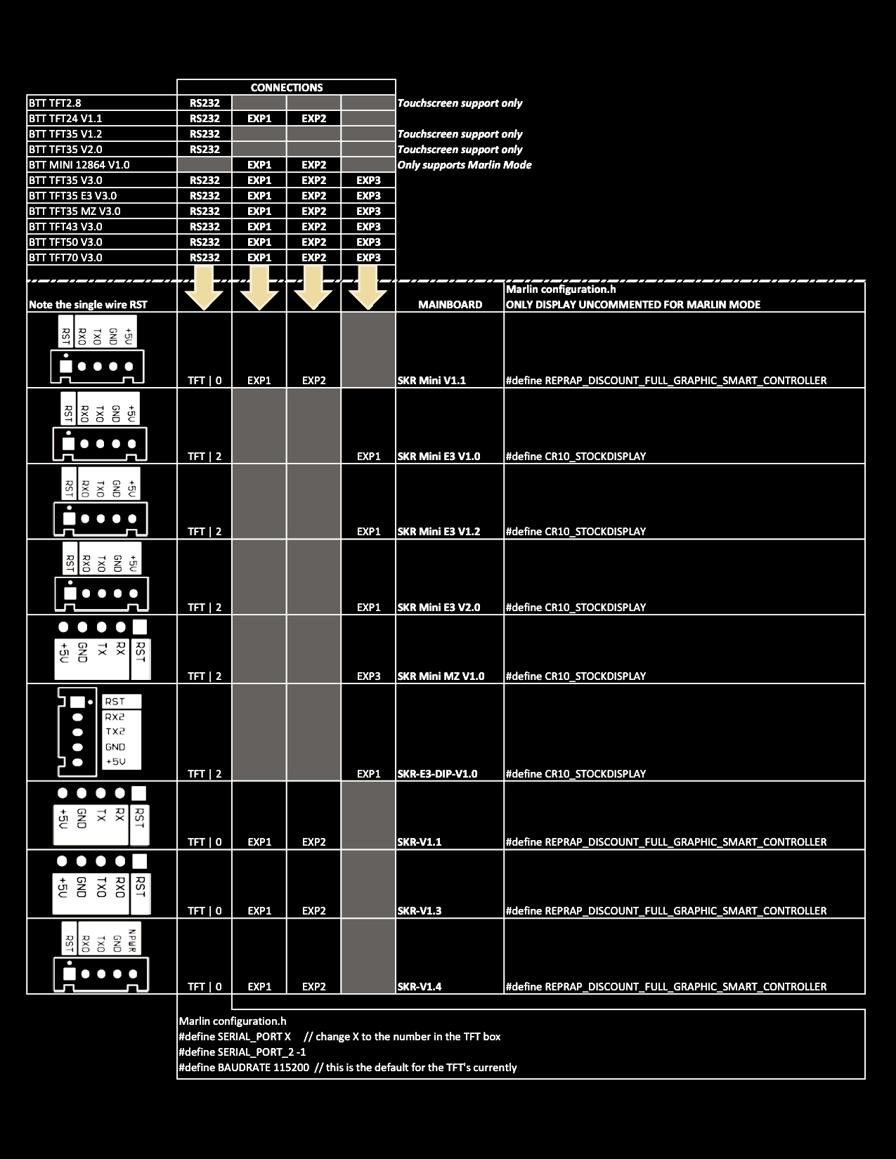
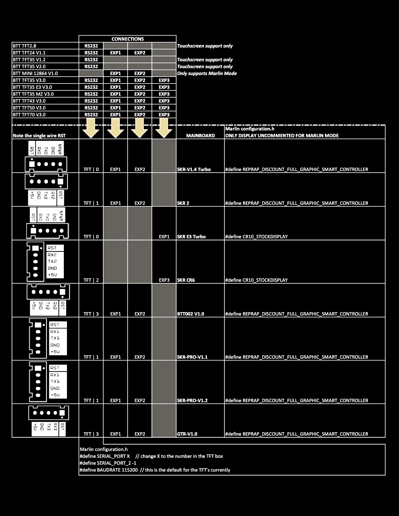
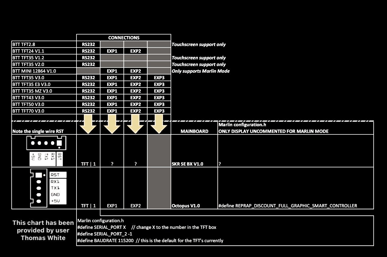
Do the following, to be able to use the touchmode of your screen.
- Connect the 5pin serial cable according to the manual of your mainboard.
- Define a serial port in Marlin, to activate the port used by the TFT.
- Make sure the same BAUDRATE is defined in Marlin and the firmware of your TFT (config.ini)
In case one of the three points above is not done right, "No printer attached" will be shown at the top of the screen in touchscreen mode. This is because the TFT can not "see" the mainboard through the serial cable.
Do the following, to be able to use the Marlin emulation mode of your screen.
A: In case your TFT does not have an EXP connector at all (TFT28 v1 for example), you can not use the Marlin emulator mode.
B: In case your mainboard provides EXP1 and EXP2, you have to connect 2 ribbon cables connecting EXP1 and EXP2 of the mainboard to EXP1 and EXP2 of the TFT. In the Marlin firmware of your mainboard, make sure that ONLY the "REPRAP_DISCOUNT_FULL_GRAPHIC_SMART_CONTROLLER" is activated in Configuration.h and that all other controllers are Deactivated (especially the "CR10_STOCKDISPLAY").
C: In case you have an "E3" mainboard which provides a single EXP connector, you have to connect 1 ribbon cable connecting EXP of the mainboard to EXP3 of the TFT. In case your TFT does not provide an EXP3 connector but only two 10pin connectors (TFT24 v1.1 for example) you will need a "Y-split" cable with one 10pin connector on one side (for the mainboard) and two 10pin connectors on the other side (for the TFT). In the Marlin firmware of your mainboard, make sure that ONLY the "CR10_STOCKDISPLAY" is activated in Configuration.h and that all other controllers are Deactivated (especially the "REPRAP_DISCOUNT_FULL_GRAPHIC_SMART_CONTROLLER").
| Status Screen DISABLED | Status Screen ENABLED |
|---|---|
 |
 |
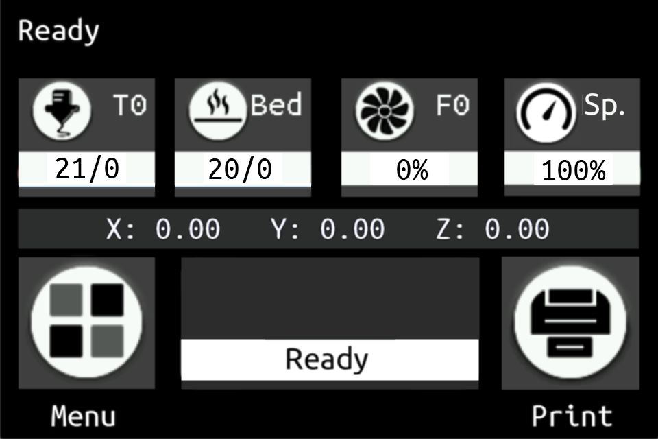
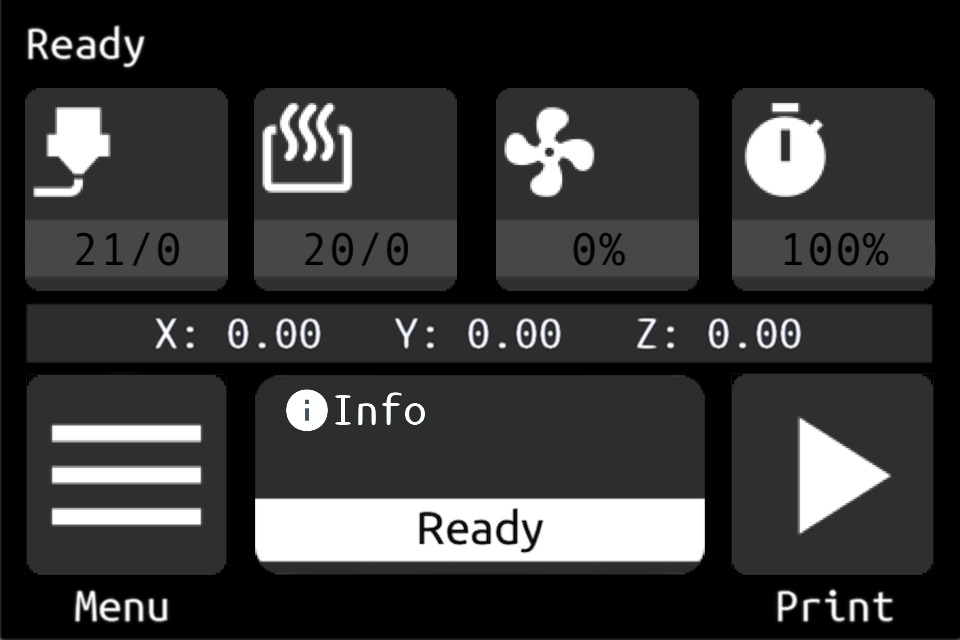
| In config.ini define: General Settings Enable Status Screen # Select the Main Screen flavour # Options: [Enable: 1, Disable: 0] status_screen: 0 |
In config.ini define: General Settings Enable Status Screen # Select the Main Screen flavour # Options: [Enable: 1, Disable: 0] status_screen: 1 |
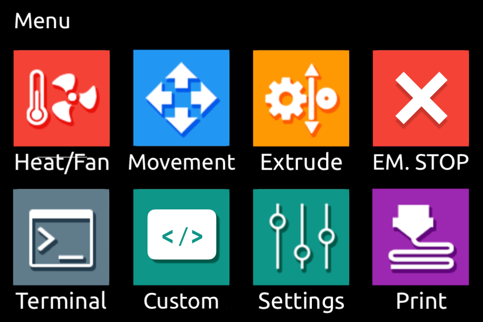
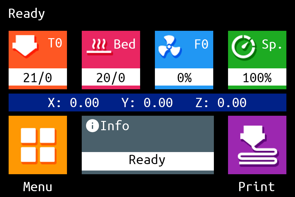
| Unified Menu Theme | The Round Miracle Theme by Acenotass |
|---|---|
|
 |
Use firmware, icons, and fonts from the Copy to SD Card root directory to update - Unified Menu Material theme folder |
Use firmware, icons, and fonts from the Copy to SD Card root directory to update - The Round Miracle theme folder |
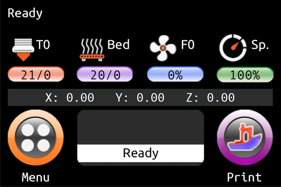
| Hybrid Red Material Theme by AntoszHUN | Hybrid Mono Material Theme by bepstein111 |
|---|---|
 |
 |
Use firmware, icons, and fonts from the Copy to SD Card root directory to update - Hybrid Red Menu Material theme folder |
Use firmware, icons, and fonts from the Copy to SD Card root directory to update - Hybrid Mono Menu Material theme folder |
| Rep Rap Firmware Dark Theme by xPew | |
|---|---|
 |
 |
Use firmware, icons, and fonts from the Copy to SD Card root directory to update - Rep Rap Firmware Dark theme folder |
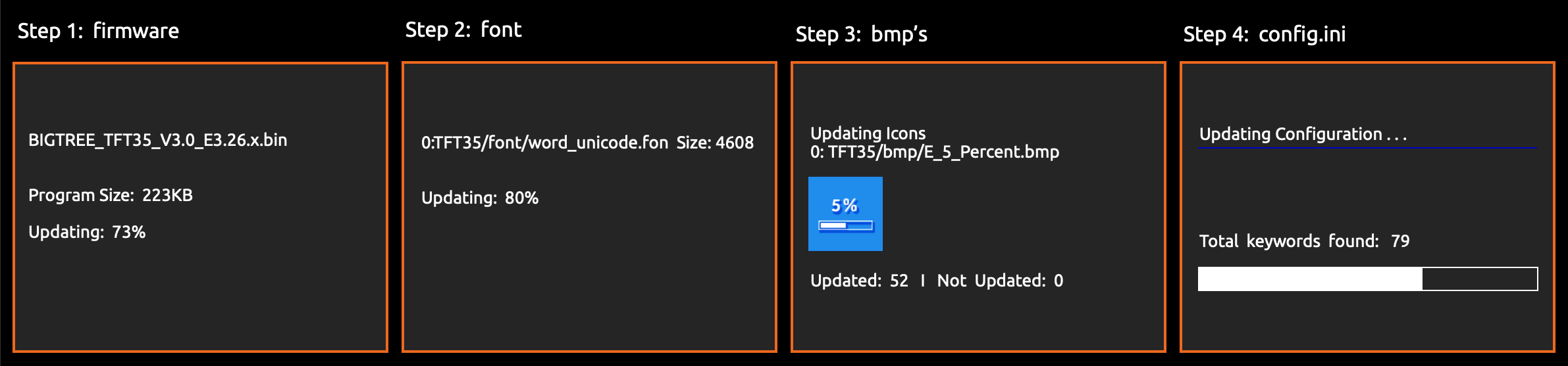
The TFT firmware update includes up to four elements and is done in three steps:
element 1: The firmware binary (BIGTREE_TFT*_V*.*.*.bin). Example: BIGTREE_TFT35_V3.0.27.bin:
BIGTREE_TFT_35: modelV3.0: hardware version27: software version
Exception: For the MKS TFT28 the binary file name must be MKSTFT28.bin.
Attention TFT35 owners. There are currently three different kinds of firmware available: V3.0, E3_V3.0 and B1_V3.0. Please make sure to use the firmware which matches your TFT screen.
element 2: Fonts and Icons (in the TFT* or MKS folder):
For BTT TFTs, the ROOT FOLDER for fonts and icons is TFT*, where * is the size of the TFT (example: TFT24, TFT35, TFT50, etc). Fonts and icons folder structure:
TFT*/font: includes the fonts in .fon format and a readme.mdTFT*/bmp: includes the icons in .bmp format and a readme.md
For MKS TFTs the ROOT FOLDER for fonts and icons must be renamed to "MKS". Fonts and icons folder structure:
MKS/font: includes the fonts in .fon format and a readme.mdMKS/bmp: includes the icons in .bmp format and a readme.md
element 3: The config.ini or (the renamed) config_rrf.ini file
Attention RepRap Firmware users. You have to make your changes using the config_rrf.ini file and rename it to config.ini before you upload it to the TFT.
element 4 (optionally): One or several language file(s)
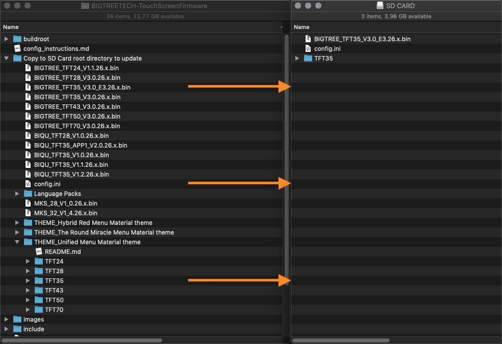
step 1: Copy your self compiled firmware or the BIGTREE_TFT*_V*...bin, plus the TFT` folder* of your preferred Material theme as well as the config.ini to the root of a blank SD card that is <8GB and formatted as FAT32:
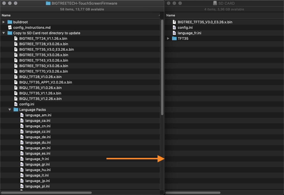
Optionally, copy one or several language.ini file(s) from Copy to SD Card root directory to update/Language Packs folder onto the SD card. Doing so will allow you to switch between English and the uploaded language(s), using the corresponding Language function of the TFT. We recommend to upload the minimum amount of languages, to keep the memory usage low. The language.ini file can be edited to change the text shown on the TFT.
step 2: Place the SD card with the BIGTREE_TFT*_V*.*.*.bin, theTFT* folder and the config.ini into the TFT's SD card reader and reset your TFT (or optionally - power cycle your printer) to start the update process.
A successful update looks like this on the screen:
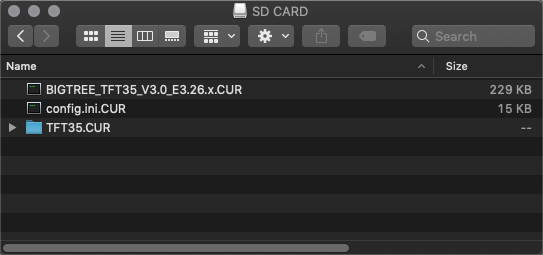
... and the name of the elements on the SD card changes to this:
In case one or several parts of the update failed, an error will be shown. Follow the information on the screen to update the missing or outdated elements.
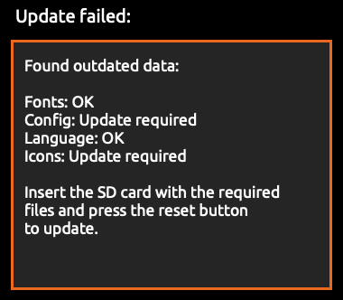
After the update is done and the files are renamed, it is possible to reuse them again. To do so, change the name of the element(s) to the pre-update name and start the update process again.
step3: Remove the SD card from the TFT and restart the printer.
Tip: Format the SD card after the firmware update in case you would like to print from it.
Sometimes a calibration will be executed automatically after a firmware update, showing a white screen with a red dot in the upper right corner and the text: Touch Screen Calibration - Please click on the red dot. To calibrate the screen press with your finger or a stylus the red dot in the upper left corner, then the red dot in the upper right corner and then the red dot in the lower right corner. Even the screen asks you to press the red dot, press the black dot in the middle of the screen to finish the calibration. Repeat the process in case the message: "Adjustment failed, please try again" is shown.
Attention RepRap Firmware users. You have to make your changes using the config_rrf.ini file and rename it to config.ini before you copy it to the TFT.
The Firmware can be modified by changing the config.ini (or the renamed config_rrf.ini) file from: Copy to SD Card root directory to update using a simple text editor (make sure to use UTF encoding).
Once saved, it can be uploaded without the need to upload the firmware or the TFT folder again, as long as the firmware and the config file are from the same version.
To edit the config file follow the instruction here: Detailed Instructions here
To update the Firmware configuration:
-
Edit the settings like described above
-
Copy the config.ini file to the root of the SD card. (The SD card capacity should be less than or equal to 8GB and formatted as FAT32)
-
Insert the SD card into the TFT's SD card slot and restart the printer or press the reset buttion of the TFT.
-
The TFT will update and store the configuration from the configuration file.
-
Make sure to remove the SD card from the TFT and restart the printer.
-
On the TFT click on Menu - Settings - Feature and navigate to the last page. Click on
"Reset default settings ..."
-
Restart the printer to finish the update
See Customisation guides for detailed information.
View full instructions
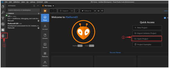
- Setup Visual Studio Code with PlatformIO instructions
- Click on the PlatformIO icon (①) and then click on Open Project (②):
- Find the BIGTREETECH firmware source directory , then click Open:

- After opening the project, edit
platformio.iniand change thedefault_envsto one that matches your TFT model and version:;BIGTREE_TFT35_V1_0 ;BIGTREE_TFT35_V1_1 ;BIGTREE_TFT35_V1_2 ;BIGTREE_TFT35_V2_0 ;BIGTREE_TFT35_V3_0 ;BIGTREE_TFT35_E3_V3_0 ;BIGTREE_TFT28_V1_0 ;BIGTREE_TFT28_V3_0 ;BIGTREE_TFT24_V1_1 ;MKS_TFT32_V1_3 ;MKS_TFT32_V1_4 ;MKS_TFT32_V1_4_NOBL ;MKS_TFT28_V3_0 ;MKS_TFT28_V4_0 ;MKS_TFT28_NEW_GENIUS [platformio] src_dir = TFT boards_dir = buildroot/boards default_envs = BIGTREE_TFT35_V3_0
- Click the check mark (✓) at the bottom of VSCode or press
Ctrl+Alt+B(Windows) /Ctrl+Option+B(macOS) to compile.
- A
BIGTREE_TFT*_V*.*.*.binfile will be generated in the hidden.pio\build\BIGTREE_TFT*_V*_*folder. Follow the update process outlined in the About TFT Firmware section above to update your TFT to the latest version.
Tip: In case there is a problem compiling the TFT firmware try to restart VSC. If this does not help and you are using macOS, delete the packages and platforms folder which you can find here: /Users/username/.platformio/.
In case the upload of a new firmware failed
First, verify that you have been using the firmware which matches your TFT. After that, try to upload the firmware, the config.ini and the TFT** folder again (like described above) using a new SD card - 8GB or smaller, FAT32 formatted. Some uploads worked fine after executing a low level format of the SD card and not a quick format.
Simple Reset
To reset the TFT's touch screen calibration, create a blank file named "reset" with the file-extension "txt", and place it in the root folder of an SD card (the SD card capacity must be less than or equal 8GB and formatted as FAT32). Insert the SD card into the TFT's SD card reader and power cycle your printer or restet your TFT to start the reset process.
Worst Case Scenario
In case the screen remains black or the brightness is not stable, the screen does not react after pressing a button or executes clicks by itself or does something similar - and the reset described above did not help - do the following. Remove the TFT from the enclosure and disconnect everything from the TFT, including the cable to the mainboard. Cut a USB cable you do not need anymore and connect the red and black wire to 5V and GND of the TFT. Do not use the unshielded wires directly but use a 2 pin connector instead. Power up the TFT and try to reset the TFT or to instal a new firmware like described in this document. With only power supplied, you should be able to navigate through the menus using the touchscreen and even to switch to Marlin Emulation (if available), even the Marlin Emulation screen will not show the interface with a proper EXP based connection.
See BIGTREETECH-TouchScreenFirmware/releases for a complete version history.
<<<<<<< HEAD
- Possibility to define CNC_MENU in Configuration.h in order to configure the SW for CNC purposes
- Introduced new language and icons tags for CNC specific menu items (no impact on 3D printer tags)
- Added some specific bitmaps (from BlomsD / MPCNC-TFT35-V2.0)
- Introduced a new menu spindle.c in order to add spindle start/stop control
- Removed Bed and Extruder Heating menu items from Mainpage.c
- Forced configuration in order to remove persistent Bed/Extruder temperature indication on all the pages
- Modified the Home menu in order to support G28 XY and G28 Z and Zero axes
- Possibility to define CNC_LASER in configuration.h in order to introduce menù for laser management (instead of fan)
See:
2.TFT35 Home Menu (Home Z - Zero 0)
3.TFT35 Home Spindle (Spindle ON/OFF)
=======
Octoprint can optionally trigger some actions to the TFT sending specific gcodes. The following actions and the related triggering gcodes are currently supported by the TFT fw:
start: M118 A1 P0 action:print_start
end: M118 A1 P0 action:print_end
cancel: M118 A1 P0 action:cancel
pause: M118 A1 P0 action:pause
resume: M118 A1 P0 action:resume
time remaining progress: M118 A1 P0 action:notification Time Left hms (e.g. 02h04m06s)
M117 Time Left hms file data progress:
M118 A1 P0 action:notification Data Left / (e.g. 123/12345) M117 Data Left /
When the trigger "print_start" is received, the TFT switches to Printing menu. Once on Printing menu, the "pause", "resume" and "stop" buttons on the menu will be disabled. That means only Octoprint will control the print. Only on print end or cancel the TFT Printing menu is finalized (statistics available etc...) and unlocked (it can be closed).
NOTE: A new plugin on Octoprint implementing the above protocol should be the preferable way (available to everyone)
The TFT is able to display embedded gcode thumbnails in the file list viewer using two different flavors: Bigtreetech-style or PrusaSlicer-style.

The first type is to store the thumbnails at a specific location in the gcode file using a dedicated Cura plugin or external post-processing script. The thumbnail's image data is raw encoded in a format which can be displayed on the TFT without any complex image transformations. Displaying these embedded thumbnails at the TFT is the fastest approach and suitable for all different BigTreeTech's TFT variants. Downside is that you either need a dedicated plugin, for example the BTT 3D Plug-In Suit, or you have to use the post-processing script.
The other type is to store the thumbnails using dedicated comments (thumbnail begin... and thumbnail end) which is implemented in stock by some slicers like Prusa-Slicer.
The thumbnail's image data is a PNG file encoded in Base64 which cannot be displayed directly on the TFT:
A base64 decoding and png decoding needs to be performed which is quite complex for the TFT.
Displaying these thumbnails is slower but more flexible.
Due to the memory requirements it is not suitable for all the different TFT variants (only for those with RAM_SIZE > 96).
Thumbnail generation needs to be specifically enabled in Prusa-Slicer. Under Printer Settings at the G-code thumbnails settings you have to enter the specific required thumbnail image size for your TFT.
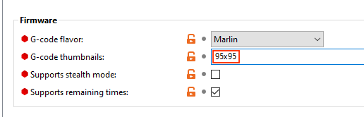
Thumbnail image sizes are:
70x70: TFT24 / TFT2895x80: TFT43 / TFT5095x95: TFT35160x140: TFT70
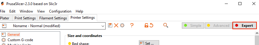
If this setting is not visible within the Prusa-Slicer you need to enable Expert Settings Mode:
Overview:
The most recent version of the standard bigtreetech TFT firmware has built in support for RepRapFirmware. The pre-built images have this enabled by default.
Loading the firmware:
There is now an RRF config.ini It needs to be renamed from config_rrf.ini to config.ini for flashing of the firmware.
Config.g Changes:
Add the following line to your config.g to enable the screen: M575 P1 S2 B57600
Implemented features:
Auto detect fw type + separate config.ini for easier setup -Temperature/movement/cooling status monitoring and control
- Print status monitoring with mid-print tuneing/pausing
- Macro support
- Print from onboard/external SD card
- Please see RRF further tweaks #2278 for more information.
Menu system for macros:
- Thumbnail and menu system support for onboard gcodes
- Load/unload menu
- PID tune menu
The following mainboards are covered by this document.
MKS GEN_L v1.0, MKS SGEN (LPC1769), MKS SGEN_L v1.0 (LPC1768) and MKS SGEN_L v2.0 (LPC1769)
Connections
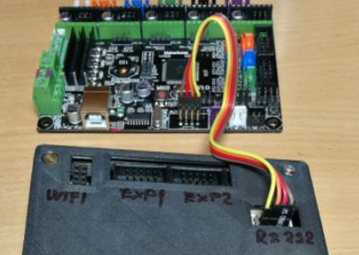
The TFT35 E3 V3.0 has 3 cables to connect to the mainboard. Two 10 pin ribbon cables and one 5 pin serial cable. The 2 ribbon cables connect to the EXP1 and the EXP2 connections on both the TFT35 E3 V3.0 and the MKS mainboards.
The RS232 cable is connected to the RS232 connection on the touchscreen, with the other end connecting to the AUX1 connection on the mainboard. The RS232 cable has 5 wires. One end has a single 5 wire connector that goes to the RS232 connector on the touchscreen, and the other end has two connectors, one has 4 wires, and the second one has one wire. That single wire is for the Reset and is not used on these MKS mainboards. The 4-pin connector plugs into the AUX1 connection. It must connect to the top row of pins when looking at the socket with the notch facing away from the mainboard and must be also plugged in with the 5v+ wire connected to the first pin in the upper left corner of the socket. The RESET wire is not connected to anything.
NOTE: On the MKS mainboards there is an issue that involves at least the MKS GEN_L, MKS SGEN, and MKS SGEN_L models. The EXP1 and EXP2 connections have the socket shell installed wrong way around. The notch that indexes the cable should be facing towards the mainboard. If you get a blank screen on the TFT35 E3 V3.0 touchscreen after connecting the two EXP cables and turning the printer on, turn printer off and disconnect the 10 pin cables from either the touch screen or the mainboard and using small diagonal cutters trim the tab down to be as close to flush as you can get on both cables (and only on one end) and plug them back in with the trimmed tab now facing the mainboard.
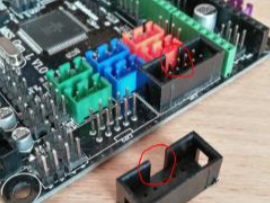
The second workaround for this issue is to carefully pry the two shells surrounding the pins on the mainboard upwards until they clear the pins. Do NOT use a metal tool for this, use a sturdy plastic or whalebone prying tool. Turn the shell 180 degrees and align the pins with the holes in the shells and push the shells back on with your thumb. Do not push the shell back on with something that could cause damage if it were to slip. Once the shells are installed you can use the stock (unaltered) cables as they are.
Firmware
Edit the configuration.h file and enable the line that says: #define REPRAP_DISCOUNT_FULL_GRAPHIC_SMART_CONTROLLER Rebuild and deploy the Marlin firmware to your 3D Printer.
Statistics as filament length, filament weight and filament cost can be embedded into the gCode. After the print is finished there will be an infobox that you can click and a popup will present you the printed filename (limited to the first 25 characters), the time needed for the print, the filament length used, the filament weight and its cost. In the case of multi-filament usage the statistics will show the sum of all individual data (sum of length, sum of weight, sum of cost). The statistic data in the gCode must have the following format (a good practice would be to include this at the beginning of the gCode):
M118 P0 filament_data L:{12.3456}mL: represents the length in metersM118 P0 filemant_data W:{1.23456}gW: represents the weight in gramsM118 P0 filament_data C:{0.1234}C: represents the cost without a unit
The values of every filament data can be in a brackets, parentheses, apostrophes, etc. or without them, measurement units can be there or not.
So M118 P0 filament_data L:(12.3456)m, M118 P0 filament_data L:12.3456meters, M118 P0 filament_data L:[12.3456] and so on are all valid formats.
For multi-filament print statistics the data for each used filament should be written, they can be separated by comma, space, asterix, whatever, except ";" and ".".
Examples for multi-filament:
M118 P0 filament_data L:(12.3456, 8.2520974)mM118 P0 filament_data W: 24.87652 15.568264 grammM118 P0 filament_data C:[1.3456], [0.56024]
The inclusion of the filament data into the gCode can be automated. In Cura all you have to do is to insert the following into the Start G-Code:
M118 P0 filament_data L:{filament_amount}mM118 P0 filament_data W:{filament_weight}gM118 P0 filament_data C:{filament_cost}
In case the gCode file has been generated using the BTT 3D Plug-In Suit, the data is automatically added.
In case filament data is not present in the gCode, the filament length data is calculated during print. Length is calculated regardless of using the TFT USB, TFT SD or the onboard SD. Calculations are done in both absolute or relative extrusion mode. Filament data takes into account the flow rate also but with a caveat. It has to be the same flow rate during the entire time of the printing, because the end result is calculated based on the flow rate at the time the print has finished. If flow rate changes during the print the results will not be accurate anymore.
btt_main/master