
Gigaset-Debug-Adapter can be used with many Gigaset DECT phone models to access the internal UART.
It's basically a 1.8V USB->UART converter, with switchable strapping logic and 3V step-down converter.
dialog-cr16c-uart-boot can be used to upload a stub to the phone through the boot ROM and access the SPI NOR flash chip.
gigaset-debug.mp4
The PCB can (and should) be assembled at JLCPCBs assembly service.
Manufacturing files for the automatic assembly service can be found at gerbers/RevB/Gigaset-Debug-Adapter/.
JLC can probably also manufacture the 3D printed adapter for you, altough this was never tested. Please report if you do.
Additionally, you will need:
- 2 Pogo pins. Tested with: 16,7 mm full length, 2,3 mm travel, 0.96 mm diameter
- 2 Keystone 5230 AAA battery contacts (2 slim pieces of tin sheet would probably work as well)
- 2 M3 threaded inserts (designed for CNCKitchen M3 x 5.7)
- 2 M3 machine screws
- 1 3D printable battery adapter (FDM with 0.3mm layer height, 35% infill worked well. Print upside down!)
Note: We've had trouble soldering to the Keystone 5230 using lead-free solder! Use leaded solder instead.
sysmocom is making available a complete kit consisting of all the parts listed above which can be purchased via the sysmocom webshop
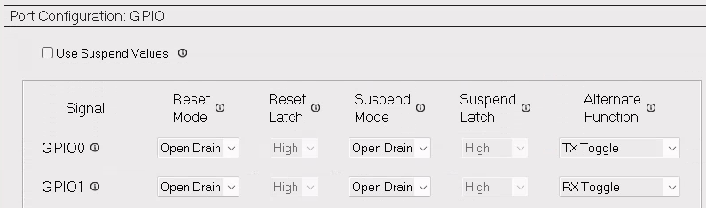
In order to enable the RX/TX LEDs, the internal EEPROM of the CP2102N USB->UART converter IC must be programmed to use the GPIO0 and GPIO1 pins as LED outputs. This can be done eiher
- using SiLabs propritary Simplicity Studio,
- using the FOSS tool ext/badge/cp2102 of cp210x-program
Simplicity Studio (and the experience of downloading it) is awful, be prepared and use a VM.
This step is fully optional, you just lose the LEDs. Those are pretty and useful, but not required.
The FOSS tool cp210x-program contains two separate programmers:
One python tool for CP2102, and the ext/badge/cp2102 C program which we need here.
Do something like
./bin/cp2102 -p "Gigaset Debug Adapter" -g on
And then power-cycle the board to apply the new settings.
Schematic - Rev. B
Bootloader utility - dialog-cr16c-uart-boot
Rev.A: Bootloader Resistor logic is wrong, use Rev.B!
The battery adapter was designed using OpenSCAD. The definition file can be found as battery-adapter.scad.
OpenSCAD will generate a .stl file, suitable for 3D printing. This file can be converted for use in KiCad using meshconv:
meshconv -c wrl battery-adapter.stl -o battery-adapter